Highly integrated Single Chip Frequency Converters
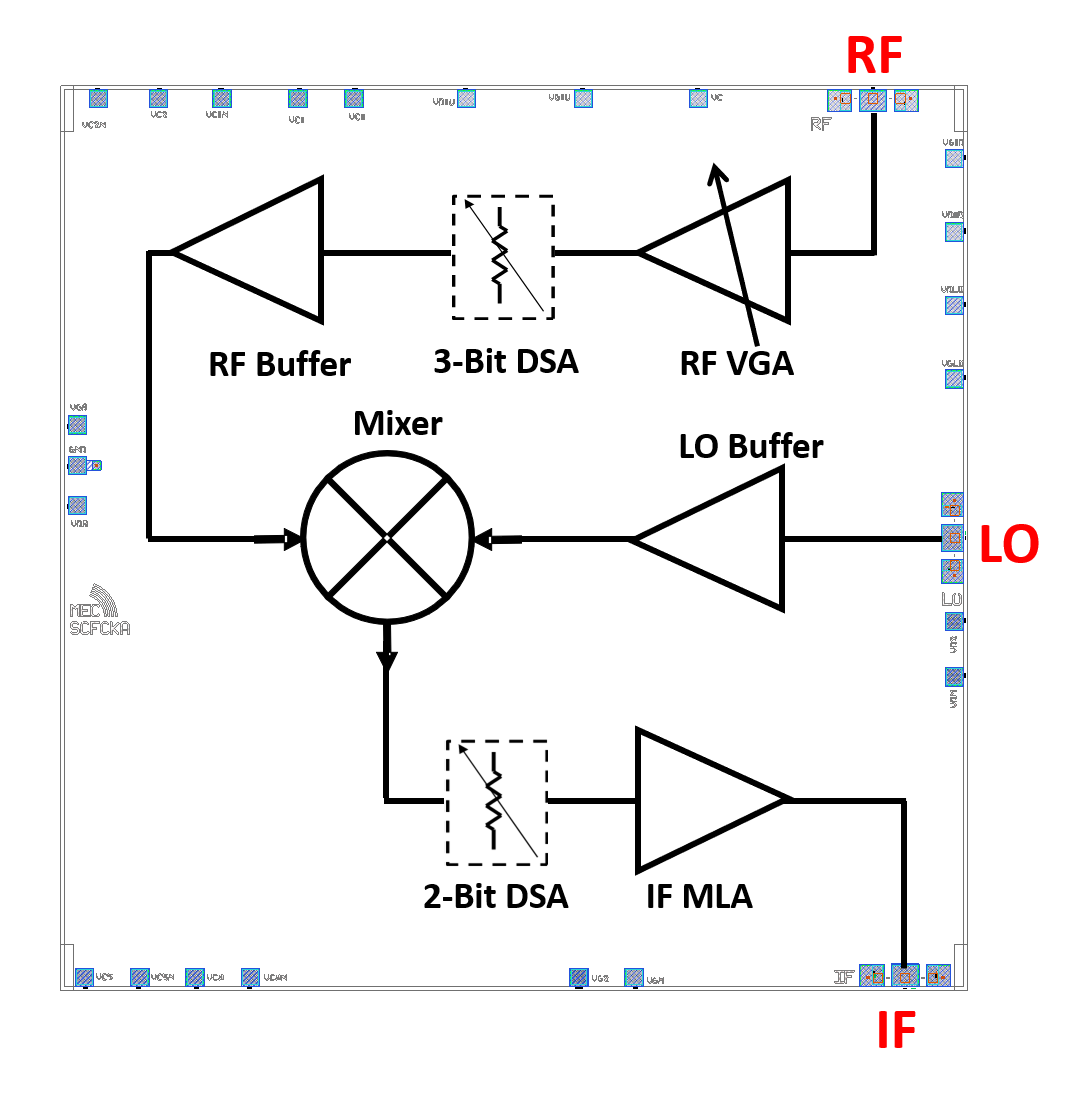
A family of full frequency converters, highly integrated into single MMICs, have been developed allowing a radical simplification of telecom satellite architecture and meeting the tight requirements of new systems in terms of performances, dimensions and costs. To do that, the main functions of a standard converter are combined in the single chip, providing additional features to the frequency conversion.
Two different chipsets are available: one made of two downconverter MMICs, the MECKaSCFC and the MECKuSCFC, available in bare-die option and designed to perform the translations Ka-to-Ka and Ku-to-Ku, respectively, and one composed by two downconverters, MECSCDCA and MECSCDCA, and one upconverter, MECFCIFKUP, in hermetic package solution, operating in the ranges Ka/Ku and IF (1 – 5.5 GHz).
The MECKaSCFC and the MECKuSCFC integrate in a single MMIC up to 8 different operating blocks to provide, in addition to the frequency conversion, programmable Gain control, compensation of gain variation over temperature, RF, IF and LO signals amplification. They generate the translation (27.5 – 30 GHz) to (17.2 – 20.2 GHz) and (13 – 14.5 GHz) to (10.7 – 12.7 GHz), respectively, maintaining an output TOI of about 33 dBm.
The two hermetically packaged downconverters MECSCDCU and MECSCDCA integrate in a single chip two states of gain in the conversion chain, as well as a continuous gain variation of the LO buffer amplifier, while converting the frequency bands (12.5 – 15 GHz) and (27 – 31 GHz) to the IF band (1 – 5.5 GHz), respectively. The upconverter MECFCIFKUP integrates the same features of the previous ones but, in this case, the low frequency signal in the range (0.5 – 2.5 GHz) is translated up to the Ku band (10.5 – 13 GHz).
| Specifications | MECKuSCFC | MECKaSCFC | MECSCDCU | MECSCDCA | MECFCIFKUP |
|---|---|---|---|---|---|
| RF_in frequency | 13 – 14.5 GHz | 27.5 – 30.0 GHz | 12.5 – 15 GHz | 27 – 31 GHz | 10.5 – 13 GHz |
| LO frequency | 1.5 – 3.3 GHz | 4.5 – 6.2 GHz | 8.5 – 12.5 GHz | 11.5 – 14.5 GHz | 8.1 – 12.4 GHz |
| IF_out frequency | 10.7 – 12.7 GHz | 17.2 – 20.2 GHz | 1 – 5.5 GHz | 1 – 5.5 GHz | 0.5 – 2.5 GHz |
| Conversion Gain | 27 to 47 dB | 23 to 43 dB | 4 and 12 dB | 3 and 8 dB | -6.5 dB |
| LO power level | +4 dBm | +3 dBm | -7 to +2 dBm | -7 to +2 dBm | -7 to +2 dBm |
| Output TOI | 33 dBm | 33 dBm | 5 to 11 dBm | -1 to 6 dBm | 5 dBm |
| Features | 20 dB (1 dB step) + 5 dB (continuous) Gain variation | 20 dB (1 dB step) + 5 dB (continuous) Gain variation | 2 states of Gain; 9 dB of LO range | 2 states of Gain; 9 dB of LO range | 9 dB of LO range |
| Package | bare-die | bare-die | hermetic SMD | hermetic SMD | hermetic SMD |
| Dimensions | 5.0x5.0x0.07 mm3 | 5.0x5.0x0.07 mm3 | 6.0x6.0x2.2 mm3 | 6.0x6.0x2.2 mm3 | 6.0x6.0x2.2 mm3 |
| Data sheet | Download | Download | Download | Download | Download |


